RJ Systems
Linux System Administration
Home Tech Linux Links Consulting


Valid XHTML 1.0!

Valid CSS!

IPv6 test

Asterisk: ISDN BRI support with a Cologne Chip HFC-S PCI card

Introduction

One of the most reliable ways to connect Asterisk, or any Private Branch Exchange (PBX), to the Public Switched Telephone Network (PSTN) is with ISDN: Integrated Services Digital Network. In Europe, this service is available in two main flavors, ISDN-30/PRI (Primary Rate Interface) and ISDN-2/BRI (Basic Rate Interface), the latter being the more affordable and often considered a good choice for SoHo use. The main selling points of ISDN BRI are its increased connection quality, faster dialing, its ability to connect up to seven devices and carry two calls simultaneously, including three-way conference calls. It can also be used to combine two 64 kbps data connections to form a single 128 kbps connection, but this has become less interesting since the advent of cheap, broadband Internet access.

Euro-ISDN BRI connections have two 64 kbps B- (Bearer/data) channels for voice or data connections and one 16 kbps D- (Delta/control) channel for the transmission of signaling information (to connect/disconnect calls and negotiate special calling parameters, such as caller-ID, call waiting and the data protocol). In the Netherlands, ISDN has always been more popular among businesses than consumers, even though a BRI line is still less than twice the monthly cost of a typical analog line.

Plain Old Telephone Service (POTS) is the traditional, analog, voice-grade alternative to ISDN. But not only is it much less responsive, when using Asterisk it may be difficult to get the caller-ID (CID) to work. Various protocols exist for CID transmission, but unfortunately some are less popular than others. In countries where the telco decided long ago to use some unusual version of this protocol, many popular telephony solutions (various SIP adapters, Asterisk, etc.) may not be able to detect the CID. In such cases, ISDN, which is much more standardized in this respect, may be a solution.

HFC-S PCI chip
The HFC-S PCI A chip, with its easily
recognizable Cologne Chip logo modeled
after Cologne Cathedral.
HFC-S PCI card
One example of an HFC-S PCI card is the C128iR,
a model made by Dutch OEM, Conceptronic.

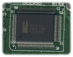
There are more than a few ISDN BRI cards that are supported by Asterisk, but few are as affordable, or as widely available, as the HFC-S PCI cards with their easily recognizable Cologne Chip logo. And, while modules for many of the more exotic ISDN cards must be obtained and compiled separately, support for HFC-S PCI cards is included in the zaptel-modules package, which must always be compiled for Asterisk 1.4 anyway. Not that this support can be described as particularly reliable, but it can certainly be regarded as adequate for most personal needs. Your milage may vary, but with many other ISDN BRI cards being 10-20x more expensive, there is certainly less reason to complain.

The Cologne Chip HFC-S PCI A ISDN 2BDS0 is actually a single-chip, ISDN-S controller: the first such solution available for ISDN cards. Introduced in 1996, many resellers are still marketing cards that are based on it today. The chip includes an ISDN S/T interface (sometimes referred to as the S0-bus) that allows it to be connected to an ISDN NT1 together with up to six other devices. Although it does not include an integrated NT1 as might be desired for use in North America, it is capable of operating in NT mode, which allows it to communicate directly with other ISDN user devices with a crossed cable.

The HFC-S PCI A is a controller for passive ISDN cards. Active cards handle most of the ISDN signalling information with dedicated microprocessors and firmware, which is efficient when many channels see heavy use, but it also makes the cards much more expensive. With passive ISDN cards, the same tasks are instead performed by PC software.

This article describes how to configure Debian 5.0 (lenny) and Asterisk with an HFC-S PCI card for use with an ISDN BRI connection in the Netherlands, while explaining a bit about the technology from this point of view along the way. It builds on a previous article, Asterisk: minimal SIP configuration, in which Asterisk 1.4.21, Zaptel 1.4.11 and the locally compiled zaptel-modules package were installed and configured. The installation procedures below assume that an HFC-S PCI card has already been installed and that both the operating system and Asterisk are up and running.


1. Zaptel modules

When the zaptel-modules package was compiled and installed, a number of extra modules were added to the running kernel, such as ztdummy.ko. This was described in the previous article. However, the package also includes two modules that specifically support the HFC-S PCI card: zaphfc.ko and vzaphfc.ko. This frequently complicates matters, first of all because zaphfc.ko does not work, and secondly because both of them often end up being loaded, in which case neither are likely to be functional. In addition, there are also some other modules that can conflict with the required Zaptel modules: hfc4s8s_l1, hisax and isdn.

Two things can be done to fix these problems. First, simply delete the buggy zaphfc module to ensure that only the correct one is used:

~# rm /lib/modules/`uname -r`/misc/zaphfc.ko
~# depmod
~# _

Second, prevent hfc4s8s_l1, hisax and isdn from being loaded by creating a new file, called /etc/modprobe.d/zaptel, with the following contents:

blacklist hfc4s8s_l1
blacklist hisax
blacklist isdn

Before continuing, remove these modules from memory in case they have already been loaded:

~# rmmod hfc4s8s_l1 hisax isdn
~# _

2. Zaptel config

At this point it is safe to run a script that will both (re)load the correct Zaptel modules for the HFC-S PCI card and create a hardware configuration file. In this case the command is:

~# genzaptelconf -dsc nl
~# _

This is a script that is used to generate a new Zaptel configuration file. The options used here are:

-d Detect any Zaptel modules, unload all of them and load them again one at a time.
-s Stop Asterisk before taking any actions and start it again afterwards.
-c nl Set the country-code for the tonezone entries in zaptel.conf, in this case to nl for the Netherlands. The default is us.

Running the genzaptelconf script in this way will result in two things. First, it unloads all Zaptel modules and loads them again one by one. Second, it create the Zaptel configuration file, /etc/zaptel.conf. In this case everything was detected correctly on the first attempt. Without any comments, the contents of the file look like this:

span=1,1,0,ccs,ami
bchan=1-2
dchan=3

loadzone	= nl
defaultzone	= nl

Explanation:

span=1,1,0,ccs,ami

This is the Zaptel span configuration statement, the format for which is:

span=(spannum),(timing),(LBO),(framing),(coding)
spannum=1 Sets the span number. Spans are identified by incrementing numbers starting with 1. A span is a logical unit that represents a group of channels. With digital telephony, a span usually represents a physical port on the card. This system has only one such card with a single port, so it is referred to as span 1.
timing=1 Sets the synchronization source for timing purposes. The first span is numbered "1" to make it the primary timing source on the system, accepting timing from the telco. Each additional span is given an incrementally higher value.
LBO=0 Line Build-Out (waveform transmit) value. All Zaptel LBO values other than zero are only useful with T1 lines to compensate for signal attenuation due to the length of the cable connected to an ISDN PRI card. With an HFC-S PCI card this value should always be set to zero. A table with other values exists, but these are not supported by the HFC-S PCI A chip, which does not include any LBO values. Instead, this chip is designed to work with all possible ISDN S/T configurations as described in ITU-T recommendation I.430. According to this document, with the most common cabling configuration, called the short passive bus, the maximum cable length between an NT and any terminal equipment (TE) is 100 meters when using a low impedance cable (75Ω), while lengths of up to 200 meters are possible when using a high impedance cable (150Ω) due to the lower attenuation. However, with more typical 120Ω twisted pair cabling, a maximum length of 150 meters should be attainable.
framing=ccs The type of information specified here depends on the telco and the equipment used. For T1 connections it is the (OSI layer 2) frame type: esf or d4 (Extended Super Frame or Digital 4 a.k.a. Super Frame). For E1 and BRI it is the (OSI layer 3) signalling type, cas or ccs, for the ISDN connection control protocol. With BRI, Common Channel Signaling (CCS) is used for the out-of-band transmission of signalling information over the ISDN D-channel. Its in-band counterpart, Channel Associated Signaling (CAS), is not used with BRI. For CCS, the actual network protocol used is specified in ITU-T recommendations Q.930 (I.450) and Q.931 (I.451).
coding=ami The line code type used for the transmission of voice information over the ISDN B-channels. This depends on what is used by the telco, which in this case is Alternate Mark Inversion (AMI). Also called bipolar, this is a synchronous clock encoding technique in which binary 0 is represented by the absence of an electrical charge, while binary 1 (the mark) is alternately represented by positive and negative charges. Actually a three-state signal (+V, 0V, -V), it prevents any build-up of the DC voltage level down the line; an advantage when the same wires are used to carry a small voltage to power intermediate equipment, such as line repeaters. AMI was often used in early pulse-code modulation (PCM) networks and is still used in older multiplexing equipment today. Other line codes used for BRI include 4B3T (4 Binary, 3 Ternary) and 2B1Q (2 Binary, 1 Quaternary). The latter is used mostly in North America.
bchan=1-2

Sets the range of the ISDN B-channels.

dchan=3

Sets the number of the ISDN D-channel.

loadzone=nl

Loads the indication tones (dial tone, etc.) that are used in a particular country. Multiple lines like this can be included, each for a different tonezone. The default is us.

defaultzone=nl

Sets the default tonezone to specify which country's indication tones should be used if nothing else is defined. The default is us.


3. Zap channel config

All Zap channels must be defined in the /etc/asterisk/zapata.conf configuration file before they can be used by Asterisk. The original version of this file is interesting, but contains mostly comments, so rename it for now:

~# mv /etc/asterisk/zapata.conf /etc/asterisk/zapata.conf-org
~# _

After that, create a new, empty version of this file and modify its ownership and permissions:

~# touch /etc/asterisk/zapata.conf
~# chown asterisk.asterisk /etc/asterisk/zapata.conf
~# chmod 640 /etc/asterisk/zapata.conf
~# _

Then edit the new, empty /etc/asterisk/zapata.conf and add these lines to it:

[channels]

internationalprefix=00
nationalprefix=0
switchtype=euroisdn 
signalling=bri_cpe_ptmp 
pridialplan=local
group=1 
context=incoming
channel => 1-2 

Explanation:

[channels]

Relevant section title. It may contain many channel definitions, although only one is included here. This section is often preceded by a [trunkgroups] section that is not required here.

internationalprefix=00

Prevents international calls from being missed because the dial plan is missing a variation of the phone number associated with this channel that includes two leading zeros (follow by the country code and the area code). This is necessary in many countries, including the Netherlands.

nationalprefix=0

Prevents national calls from being missed because the dial plan is missing a variation of the phone number associated with this channel that includes one leading zero (followed by the area code). This is necessary in many countries, including the Netherlands.

switchtype=euroisdn

Sets the ISDN switch type, in this case to euroisdn. The default is national (National ISDN type2), which is common in the United States.

signalling=bri_cpe_ptmp

Sets the signalling type to use with the interface. Here, it is set to Basic Rate Interface, Customer-Premises Equipment side, Point-To-Multipoint. The last part, ptmp, refers to the oft-used capacity of the S/T interface to accommodate up to eight devices (when the NT1 is also counted).

pridialplan=local

Sets a dial plan parameter. Ignored by most ISDN switches, but required in the Netherlands. Here, local is used, but unknown is also sufficient. The default, national, is not.

group=1

Allows multiple channels to be treated as one for outgoing calls, in which case the first available channel will always be used. The value used here is arbitrary, but must be matched in the dial plan.

context=incoming

The name specified here, which is arbitrary, determines where incoming calls will enter the dial plan when they arrive on this channel definition.

channel => 1-2

Defines the channel or range of channels. Each channel definition inherits all of the options stated above it in the configuration file. There must also be a matching channel or range of channels defined in /etc/zaptel.conf.

To reconfigure the Zap channel, Asterisk needs to be restarted. It is possible to reload the Zap channel module on the fly, but that will not reconfigure all of the options. So, just restart it:

~# /etc/init.d/asterisk restart
Stopping Asterisk PBX: asterisk.
Starting Asterisk PBX: asterisk.
~# _

4. OS-level diagnostics

The output from the lspci -vv should include something like:

00:0d.0 Network controller: Cologne Chip Designs GmbH ISDN network controller [HFC-PCI] (rev 02)
	Subsystem: Cologne Chip Designs GmbH ISDN Board
	Control: I/O- Mem+ BusMaster+ SpecCycle- MemWINV- VGASnoop- ParErr- Stepping- SERR- FastB2B- DisINTx-
	Status: Cap+ 66MHz- UDF- FastB2B- ParErr- DEVSEL=medium >TAbort- <TAbort- <MAbort- >SERR- <PERR- INTx-
	Latency: 16 (4000ns max)
	Interrupt: pin A routed to IRQ 11
	Region 0: I/O ports at eff0 [disabled] [size=8]
	Region 1: Memory at fe700000 (32-bit, non-prefetchable) [size=256]
	Capabilities: [40] Power Management version 1
		Flags: PMEClk- DSI+ D1+ D2+ AuxCurrent=0mA PME(D0+,D1+,D2+,D3hot+,D3cold-)
		Status: D0 PME-Enable- DSel=0 DScale=0 PME+
	Kernel driver in use: vzaphfc
	Kernel modules: vzaphfc, hisax

Among other things, this shows that the card is being run by vzaphfc; one of a number of kernel modules that are shown to be loaded by the lsmod command:

Module                  Size  Used by
xpp                   124896  0
vzaphfc                20632  3
firmware_class          6816  0
zaptel                185060  10 xpp,vzaphfc
crc_ccitt               2080  1 zaptel

These modules are:

xpp XPP Zaptel Driver.
vzaphfc HFC-S PCI A Zaptel Driver.
firmware_class Multi purpose firmware loading support.
zaptel Zapata Telephony Interface.
crc_ccitt Support for CRC-4 calculations; necessary in this case for the D-channel FCS. This CRC is also known as the ITU-CRC, while the ITU-T was previously called the CCITT.

5. Zaptel diagnostics

Retrieve some diagnotic information regarding the new card and its status. The first method is simply involves reading a file in the /proc directory structure:

~# cat /proc/zaptel/*
Span 1: ZTHFC1 "HFC-S PCI A Zaptel Driver card 0 [TE]" (MASTER) AMI/CCS 

	   1 ZTHFC1/0/1 Clear 
	   2 ZTHFC1/0/2 Clear 
	   3 ZTHFC1/0/3 HDLCFCS 
~# _
  • This shows the single ISDN BRI span that was configured in the previous step. Other cards may have multiple spans, each with either one channel, such as with analog, or many more channels, such as with ISDN PRI. The first span is Span 1, the second Span 2, etc.
  • The Zaptel module names the first HFC-S span "ZTHFC1", the second "ZTHFC2", etc. The cards are numbered card 0, card 1, etc.
  • TE stands for Terminal Equipment. This is actually a TE type 1 (TE1) device, since it connects directly to the 4-wire ISDN S/T interface. A TE2 device is anything that connects indirectly to the S/T interface through a TE1.
  • This card is described as MASTER, because it is the primary timing source for the system, although it actually receives its timing information from the telco. Additional cards are given no such description.
  • AMI/CCS: the line coding method (AMI) and a signalling type (CCS) that are used together for ISDN BRI services in the Netherlands.
  • This span has three channels, all of which look to be available, or else "(In use)" would follow each channel description. That would be the case if e.g. Asterisk was running and configured to use them.
  • The channels described as Clear are B-channels, because they carry no signaling or anything; the data they carry can be read "as is" by the software layers above.
  • The channel described as HDLCFCS is the D-channel. This is displayed when the Zaptel driver detects High-level Data Link Control (HDLC) frames that include an Frame Check Sequence (FCS): a checksum used to verify the integrity of the data (payload). For HDLC, the FCS is the ITU-CRC (CRC-4).

At the data link layer (OSI layer 2), ISDN uses two variants of the Link Access Procedure (LAP): LAP D-channel (LAPD, defined in ITU-T Q.920 and Q.921) for the D-channel, and LAP Balanced (LAPB) for data connections over the B-channels. Actually, LAP was the original data link protocol for X.25 before it was replaced by LAPB. Because both LAPB and LAPD are derived from HDLC, the Cologne Chip HFC-S processes both protocols using six hardware HDLC controllers (send and receive for each channel). LAPB, however, is irrelevant for Asterisk, because when the B-channels are used for voice they carry no signaling at all: they are clear. This is also why it is necessary to specify a line coding scheme for the B-channels.

The other is a diagnostic utility is ztscan, which prints configuration information of Zaptel spans:

~# ztscan
[1]
active=yes
alarms=OK
description=HFC-S PCI A Zaptel Driver card 0 [TE]
name=ZTHFC1
manufacturer=
devicetype=
location=
basechan=1
totchans=3
irq=0
type=digital-
syncsrc=0
lbo=0 db (CSU)/0-133 feet (DSX-1)
coding_opts=AMI
framing_opts=CCS
coding=AMI
framing=CCS

Although the command may be followed by specific span numbers, by default ztscan prints out information on all available spans. The type here is digital (as opposed to analog, which is also possible), while the status is "active" with alarms "OK." The other settings are the same as explained above.


6. Asterisk diagnostics

Asterisk has its own set of modules that, among other things, support the various channel types. One of them is the Zap channel module that allows Asterisk to communicate with the Zaptel device driver. This is how it accesses Zaptel telephony interface cards, including the HFC-S PCI card. Use this command to show which Zaptel modules are currently loaded:

~# asterisk -rx "module show like zap"
Module                         Description                              Use Count
app_zapateller.so              Block Telemarketers with Special Informa 0
chan_zap.so                    Zapata Telephony                         0
app_zapbarge.so                Barge in on Zap channel application      0
app_zapras.so                  Zap RAS Application                      0
app_zapscan.so                 Scan Zap channels application            0
codec_zap.so                   Generic Zaptel Transcoder Codec Translat 0
6 modules loaded
# _

Display general status information on all ISDN spans:

~# asterisk -rx "pri show spans"
PRI span 1/0: Provisioned, Up, Active
~# _

It may be a little confusing, but the above command also works for BRI spans. So, a variation of it to reveal more detailed information about a specific ISDN span also works:

~# asterisk -rx "pri show span 1"
Primary D-channel: 3
Status: Provisioned, Up, Active
Switchtype: EuroISDN
Type: CPE (PtMP)
Window Length: 0/7
Sentrej: 0
SolicitFbit: 0
Retrans: 0
Busy: 0
Overlap Dial: 0
T200 Timer: 1000
T203 Timer: 10000
T305 Timer: 30000
T308 Timer: 4000
T309 Timer: -1
T313 Timer: 4000
N200 Counter: 3

~# _

Show the status of all Zaptel cards:

~# asterisk -rx "zap show status"
Description                              Alarms     IRQ        bpviol     CRC4      
HFC-S PCI A Zaptel Driver card 0 [TE]    OK         0          0          0         
~# _

Show the status of all Zaptel channels:

~# asterisk -rx "zap show channels"
   Chan Extension  Context         Language   MOH Interpret
 pseudo            isdn-in                    default
      1            isdn-in                    default
      2            isdn-in                    default
~# _

Show the status of one specific Zaptel channel:

~# asterisk -rx "zap show channel 1"
Channel: 1
File Descriptor: 19
Span: 1
Extension: 
Dialing: no
Context: isdn-in
Caller ID: 
Calling TON: 0
Caller ID name: 
Destroy: 0
InAlarm: 0
Signalling Type: ISDN PRI
Radio: 0
Owner: <None>
Real: <None>
Callwait: <None>
Threeway: <None>
Confno: -1
Propagated Conference: -1
Real in conference: 0
DSP: no
Relax DTMF: no
Dialing/CallwaitCAS: 0/0
Default law: alaw
Fax Handled: no
Pulse phone: no
Echo Cancellation: 1 taps unless TDM bridged, currently OFF
PRI Flags: 
PRI Logical Span: Implicit
Hookstate (FXS only): Onhook
~# _

7. Dial plan

Assuming the ISDN line is associated with phone number 0715556789, modify the existing Asterisk dial plan, /etc/asterisk/extensions.conf, as follows:

[incoming]
exten => 0715551234,1,Goto(sp,1)
exten => 0715556789,1,Goto(sp,1)

exten => sp,1,Dial(SIP/sip-phone,60)
exten => sp,n,Hangup()

[outgoing]
exten => 0653123456,1,Dial(ZAP/g1/0653123456)
exten => 0653123456,n,Hangup()

exten => _X.,1,Dial(SIP/${EXTEN}@provider)
exten => _X.,n,Hangup()

Explanation:

[incoming]

Just as with incoming calls from the SIP channel, those from the ZAP channel range "1-2" are also inserted at this point, because the title of this section matches the context=incoming statement in /etc/asterisk/zapata.conf for that channel range. Otherwise, the name of this section is arbitrary.

exten => 0715551234,1,Goto(sp,1)

When an incoming call reaches this rule and matches extension number 0715551234, the Goto() application sends control of the current channel to extension sp with priority 1. The name of this extension is arbitrary.

exten => 0715556789,1,Goto(sp,1)

Idem, except for extension number 0715551234 − the SIP channel that was configured in the previous article.

exten => sp,1,Dial(SIP/sip-phone,60)

When an incoming call reaches this rule and matches extension sp, a sequence of two events is triggered, starting with the Dial() application, which is used to connect together all of the various channel types in Asterisk. Here, it connects the incoming SIP or ZAP channel to a SIP channel, called sip-phone, which is represented by a section called [sip-phone] in sip.conf, using a ring-timeout of 60 seconds.

exten => sp,n,Hangup()

After the call has ended, or if the ring-timeout has expired, the priority 2 (n=n+1) rule for this extension is reached. This is the Hangup() application, which simply hangs up the current channel unconditionally.

exten => 0653123456,1,Dial(ZAP/g1/0653123456)

This event is only triggered by calls that reach this point and if the dialled number matches "0653123456." The Dial() application then connects the call to the ZAP channel associated with group 1 and dials "0653123456." Notice that this rule and the next one have been inserted before the "_X." catch-all rule below − if they had been inserted after, they would never be reached.

exten => 0653123456,n,Hangup()

After the call has ended, the priority 2 (n=n+1) rule for this extension is reached and the Hangup() application hangs up the current channel unconditionally.

Once the new dial plan has been saved, submit the changes to the running Asterisk process with this command:

~# asterisk -rx "dialplan reload"
Dialplan reloaded.
~# _

8. Result

It should now be possible to receive ISDN calls for extension 0715556789 through Asterisk. This is in addition to SIP calls for extension 0715551234. In both cases, the calls will be connected on to the channel for the previously configured SIP phone.

For outgoing calls, a choice must be made in the dial plan regarding which channel to use. In this example, the ZAP channel is only used for outgoing calls if extension 0653123456 is dialled. For all other numbers the catch-all rule will apply and the SIP channel will be used.


9. See also
10. Further reading
  • Grinsing K. 2009. ISDN BRI. HTML at Network And Security.
  • ITU-T 1993. Series Q: Switching and Signalling. ITU-T Recommendation Q.920: Digital subscriber Signalling System No. 1 (DSS1), ISDN User-Network Interface Data Link Layer, General Aspects. PDF at the ITU-T.
  • ITU-T 2000. Series Q: Switching and Signalling. ITU-T Recommendation Q.920 (1993): Digital subscriber Signalling System No. 1 (DSS1), ISDN User-Network Interface Data Link Layer, General Aspects. Amendment 1. PDF at the ITU-T.
  • ITU-T 1997. Series Q: Switching and Signalling. ITU-T Recommendation Q.921: Digital subscriber Signalling System No. 1 (DSS1), ISDN User-Network Interface, Data Link Layer Specification. PDF at the ITU-T.
  • ITU-T 2000. Series Q: Switching and Signalling. ITU-T Recommendation Q.921 (1997): Digital subscriber Signalling System No. 1 (DSS1), ISDN User-Network Interface, Data Link Layer Specification. Amendment 1. PDF at the ITU-T.
  • ITU-T. 1993. Series Q: Switching and Signalling. ITU-T Recommendation Q.930 (I.450): Digital subscriber Signalling System No. 1 (DSS1), ISDN User-Network Interface Layer 3, General Aspects. PDF at the ITU-T.
  • ITU-T 1998. Series Q: Switching and Signalling. ITU-T Recommendation Q.931 (I.451): Digital subscriber Signalling System No. 1 (DSS1), ISDN User-Network Interface Layer 3 Specification for Basic Call Control. PDF at the ITU-T.
  • ITU-T 2002. Series Q: Switching and Signalling. ITU-T Recommendation Q.931 (1998): Digital subscriber Signalling System No. 1 (DSS1), ISDN User-Network Interface Layer 3 Specification for Basic Call Control. Amendment 1: Extentions for the Support of Digital Multiplexing Equipment. PDF at the ITU-T.
  • ITU-T 2003. Series Q: Switching and Signalling. ITU-T Recommendation Q.931 (1998): Digital subscriber Signalling System No. 1 (DSS1), Erratum 1. PDF at the ITU-T.
  • TechFest. 2007. ISDN Overview. HTML at TechFest.

11. Sources
  • Cisco Systems, Inc. 2009. Cisco IOS Voice Troubleshooting and Monitoring -- T1 or E1 Interface Troubleshooting. HTML at Cisco Systems.. Section: Controller Has Loss of Frame.
  • Cisco Systems, Inc. 1992-2010. Integrated Services Digital Network (ISDN) Overview. HTML at Cisco Systems.
  • Cologne Chip AG. 2001. HFC-S PCI A ISDN 2BDS0: ISDN HDLC FIFO controller with S/T and PCI interface and U-chip support. PDF at Cologne Chip.
  • Digium. Zapata.conf. PDF at Digium.
  • Digium. 2002. Zaptel.conf: How to configure the low-level Zapata Interface Library for your hardware. Linux Support Services Inc. PDF at RJ Systems.
  • Dunsmore B, Skandier T. 2002. Integrated Services Digital Network Primer: BRI. Cisco Press. HTML at Cisco Press.
  • Haden R. 1996-2010. ISDN. HTML at Data Network Resource.
  • Held G. 1999. Understanding Data Communications. Sixth Edition. New Riders Publishing. ISBN 0-7357-0036-2. 619 pp.
  • ITU-T. 1995. Series I: Integrated Services Digital Network. ITU-T Recommendation I.430: ISDN User-Network Interface, Basic User-Network Interface − Layer 1 Specification. PDF at the ITU-T.
  • Madsen L, Smith J, Sokol S. 2003. The Hitchhiker's Guide to Asterisk. HTML at MicroAlcarria, PDF at DynX Services.
  • Meggelen van J, Madsen L, Smith J. 2007. Asterisk, The Future of Telephony. Second Edition. O'Reilly & Associates, Inc. ISBN-13: 978-0-596-51048-0. 574 pp. HTML at the Asterisk Documentation Project, PDF at O'Reilly Media, Inc.
  • National Semiconductor. 1990. ISDN Basic Rate Interface Terminal Equipment (TE) System Design Guide. PDF at National Semiconductor.
  • TLS Corp. 2001. ISDN Glossary. HTML at Telos Systems.
  • Voip-Info.org. 2003-2009. Asterisk config zapata.conf. HTML at Voip-Info.org.
  • Voip-Info.org. 2004-2008. zaptelBRI. HTML at Voip-Info.org.
  • Voip-Info.org. 2005-2008. Zaptel.conf span syntax. HTML at Voip-Info.org.

12. Acknowledgements

Last modified: 2017-08-02, 17:50

©2003-2020 RJ Systems. Permission is granted to copy, distribute and/or modify the
content of this page under the terms of the OpenContent License, version 1.0.